First things first. Before we begin making anything, we will need to check that we have the following hardware at hand:
For moving the agent the following hardware is required:
- Arduino Uno rev.3
- Arduino motor shield
- Vehicle
- Ultrasonic Sensor HC_SOR04
- Mini breadboard
- x4 AA Battery
- x4 Battery Holder
- Raspberry Pi
- Wi-pi wifi dongle
- UBEC voltage regulator
- x6AA Battery holder
- Micro USB cable
The following are required in order to make an ionising chamber:
- x10 2.2k ohmsn resistor
- x10 10k ohms resistor
- x10 1m ohms resistor
- x2 MPSW45A Darlington NPN
- x2 MPSA64 Darlington PNP
- x1 100k Trimmer Pot
- x3 10k Potentiometer
- Tin
- 9v PP3 Battery
- 9v PP3 snap-on connector cable
Extras for power supply:
- 9v PP3 Battery
- x8 AA Battery
- x40 Hookup wires
Making an Ionising chamber.
Here is a step-by-step guide to making a ionising chamber. We followed this guide to make our own ionising chamber.
Details of how the components are arranged in the guts section of the diagram is covered in the 'madscientisthut' guide. It will require you to solder some parts together, and is seriously tedious I would recommend using a breadboard though we haven't in our project.
Now we have all that we need, It is time to get started !!
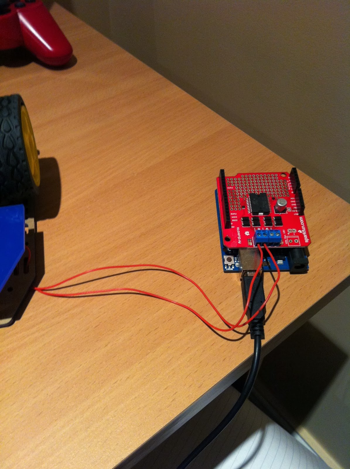
- Attach the Arduino motor shield to the Arduino Uno Rev 3.
- You would have to connect your motors to the Arduino. Here is a brief tutorial.
- Download the all the code from this folder to your PC, it will be required for later steps.
- Navigate to the Arduino website and download the Arduino IDE
- Copy the code in the file Arduino_main.c to an Arduino sketch file and upload to the Arduino.
- Boot up Raspberry pi using 'startx' command for the GUI alteration to make things easier.
- Copy the rest of directory to the raspberry pi which os running Raspbian OS.
- Run terminal and cd to the directory where the downloaded folder is.
- Type 'make', this will compile the C++ code and and create an executable file within the folder
- Type in 'make clean', to remove any unneccessary files for example .o files
- move the executable to the main directory which is entered on bootup by default for ease (you can also make the executable boot on startup).
- Finally type ./teamred to run the application (this will be done on start up every time)
- It should give an error if the arduino is not connected to the raspberry pi. It is expecting the Arduino to be connected on port ACM0/port 24 via USB connection.
Other Additional features:
- Connect the wifi dongle and login to a wireless access point (this can be done when logged into raspberry pi using the GUI alteration with 'startx' command)
- You will need to enter the following commands for some necessary installations in this order:
- sudo apt-get install ssmtp
- sudo apt-get install postfix
- When radiation has been detected and Alert will have been sent via email from raspberry pi, you can access the email alert by logging-in to the gmail account given below:
- username:raspberrypiteamred@gmail.com
- password:#raspberrypi
Setting up the hardware:
- Raspberry pi:
All that's need to do here is created a regulated power source, for our project we decided to use x6 AA batteries attach to a UBEC 3A power regulator.
The pin setting on this regulator is 5V (6V can be dangerous to the raspberry pi). This can be achieved by placing the blue cap on 5V as shown above.
I attached to power regulator's output wires to a micro USB cable, it does not have to be done like this as it can be connected directly to the GPIO ports on the raspberry pi, but i took this approach for ease.
Just showing the raspberry pi being powered by 4 AA batteries.
- Arduino:
- Motors:
Connnect the positive and negative of the motors to the arduino motor shield as shown in the images. They are set in a particular order, as positive, negative from left to right for each motor.
shown example above.
The potentiometer will be used here to pass in analog voltage readings into the Arduino to be converted into digital voltage reading on the arduino. Essentially the positive voltage source will be coming from the ion chamber, this will be shown later below.
This is me just testing the voltage readings using the default arduino sketch on the IDE.
- Ultrasonic sensor
Above is the ultrasonic sensor used
Connect the jumper wires to the Arduino and ultrasonic sensor into the requirement ports as shown above.
- Ion Chamber:
A guide on how to make this can be found the 'madscientisthut' blog.
Above is an image of all the bits and pieces needed for the ion chamber (list of all items needed is at the top of this page)
Above is the positive and negative outputs for the voltage reader on the Arduino board as mentioned above.
Other images:
Final product
the ultrasonic sensor and ion has not yet been attached


